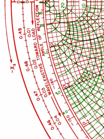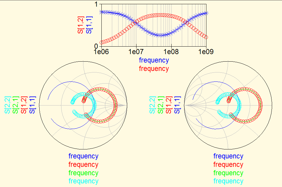

The charts were brought to limelight in the wake of World War II to evaluate the problems associated with the transmission of radio waves.Ī Smith chart can largely be identified as a diagrammatic illustration revolving around the behavior of transmission lines. It can be most importantly touted as a graphical tool or calculator that assists in displaying and understanding the impedance and frequency values associated with transmission lines with the help of equations. The chart was acknowledged as a transmission line calculator owing to its prime purpose of use. Gradually, the charts were effectively opted for various other parameters to visualize as well as analyze complexities of functions to derive accuracy and productivity in results. Example 15. Smith charts play an integral part to evaluate the impedance values of transmission lines in circuits associated with high frequency. The use of the Smith chart as an admittance chart is shown in Figure 15.10, in comparison with the impedance chart. Admittance is the reciprocal of impedance, and it is measured in siemens. Often both mappings, the admittance and the impedance plane, are combined into one chart, which looks even more confusing (see last page). The admittance chart is a mirror image of the impedance chart. Using this transformation, the result is the same chart, only mirrored at the center of the Smith chart (Fig.5).

The chart is a basically circular structure constituting of two major circles or arcs, namely the Constant R Circles and the Constant X Circles that help to visually define the shape and the data values incorporated in the chart. Essentially, there are two forms of the Smith chart: the impedance chart and the admittance chart, shown in Figure 10. In simple terms, the graph can be considered a collection of circles, where each of the circle is placed at different locations in the plot area.
Impedance and admittance smith chart series#
Here's a fundamental observation: If an impedance intersects the Re z1 constant resistance circle, then it can be matched with a series inductor or capacitor. Each of the circular structure either denotes the constant resistance or constant reactance. Using the Immittance Smith Chart, we can match any impedance (with a reflection coefficient magnitude less than 1) using a capacitor and an inductor.


 0 kommentar(er)
